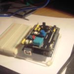
Arduino easy module shield
Equipment required:
- Shield
Arduino R3 uno
Long nose pliers
Scissors to open packet
Upon opening the packet, you get a shield with a foam protective sheet. Fitting the board is easy(ish) partly as you need to align all pins carefully and if need be adjust the to suit the female header on the Arduino Board. Clasp 1 row of pins and move slightly, be careful doing this.
inspection of the board with the Label at the bottom the digital inputs are at the bottom (near to the power in) top row viewing this way you have analogue in then the power in/out sockets.
- ax refers to analogue pins
dx refers to digital pins
so on the left hand side
pins for vcc,gnd,sda & scl
below this going down 2x switches (d2,d3)
dht 11 (d4)
below this the reset switch.
Then there are 2 LEDs blue (d13) red (d12)
Potentiometer (a0)
just above this and to the right of the switches
is a tri colour LED (d9-11)
Next to this are 2x 3 blocks pins connected to (d7 & d8) along with vcc and ground pins in. Under this there is a small buzzer connected to d5 and under that another 3 pin block with vcc,gnd and connected to a3 pin
finally on the far right hand side
serial (4x pins txd,rxd,vcc,gnd)
under that a IR led (d6)
under that light sensor (a1)
and lm35 temperature sensor connected to a2
So in all this is a pretty comprehensive board, the advantage with this is tht you don’t need to worry about wiring, you plug in the code, the components are labeled and tell you where they are connected so no messing around trying to find data-sheets or notes.
Upon connecting a usb lead for power to the Arduino the Blue LED same as the red LED on the Arduino board, which is by now covered up by the shield.
Quick test of the board using the Arduino blink example (modified)
/*
Blink
Turns on an LED on for one second, then off for one second, repeatedly.

This example code is in the public domain.
// Pin 13 has an LED connected on most Arduino boards.
// give it a name:
int led = 13;
int led2 = 12;
// the setup routine runs once when you press reset:
void setup() {
  // initialize the digital pin as an output.
  pinMode(led, OUTPUT);
pinMode(led2, OUTPUT);
}

// the loop routine runs over and over again forever:
void loop() {
  digitalWrite(led, HIGH);   // turn the LED on (HIGH is the voltage level)
  digitalWrite(led2, LOW);
  delay(500);               // wait for 1/2 a second
  digitalWrite(led, LOW);    // turn the LED off by making the voltage LOW
  digitalWrite(led2, HIGH);
  delay(500);               // wait for 1/2 a second
}


